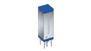
Series 125 Ultra-High Density
The smallest 2-pole reed relay in the world. The Series 125 delivers 20W, 1A switching and has an optional internal diode.
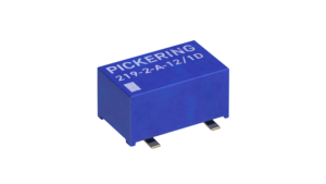
Series 219 HV SMD
Pickering's High Voltage SMD 2-pole reed relay delivers up to 1kV switching with up to 1.5kV standoff, all in a compact package.
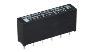
Series 144 High Power
The Series 144 is Pickering's highest power mini SIP reed relay, offering up to 80W switching at 1A, or 60W at 2A.
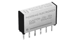
Series 109 Micro-SIL
Very small 2-pole relays at just 3.7 x 15.1 x 8.9mm. Fantastic for low-level switching. Full mu-metal package for high packing density with minimal magnetic interaction.
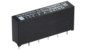
Series 104 Mini SIL up to 2kV
The Series 104 2-pole reed relays offer up to 1kV switching and up to 2kV standoff, ideal for a wide range of applications.