What Testing is Performed on Pickering’s Reed Relays?
Reed relays are a crucial part of many products that they are included in. As such, the quality and reliability of relays are directly related to the quality and reliability of the final product. Due to this, here at Pickering, we test all of our relays to the highest standards before they leave the factory.
We test several key parameters to discover if reed switches have any performance issues, as well as checking if any issues have been introduced during the packaging process. Carrying out these extensive tests, we can ensure we are meeting the high quality final product that Pickering customers have come to expect. Some typical issues that are tested for include:
- Reed blade misalignment, either from faulty switches or from disturbance to the switch during the manufacturing process.
- Failed glass seals on reed switch.
- Coil breakages.
- Coil operating voltage failures.
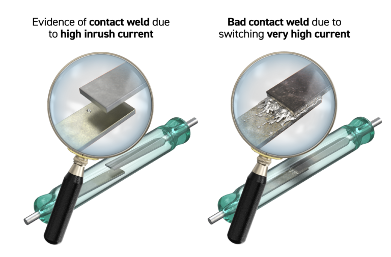
- Contact contamination or misalignment.
Revealed: the Secrets of Pickering Relay Testing Methods
All the primary characteristics are tested on every relay prior to shipment. For a long and reliable life, however, the most critical test performed is on contact resistance stability and variation. One specialist test, developed by Pickering, involves driving the relay with varying coil drive levels and measuring the changes in contact resistances that are seen as a consequence. This test will find minor contact misalignments or contamination allowing rejection of marginal parts that might otherwise become early life failures.
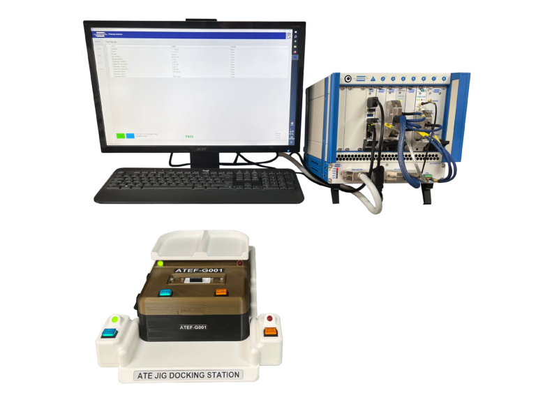
In addition to the contact stability test a full set of tests are also conducted on ATE for every Pickering relay, the example below is for a simple single pole Form A type:
- Adaptor continuity. All ATE tests are performed using a Kelvin (four terminal) connection technique. For every relay tested the fixture integrity is measured.
- StatiCoil resistance.
- Diode (if fitted). This is tested by measuring the voltage drop of the forward biased diode.
- Operate time. Time taken from the application of the coil drive to when the contact is closed.
- Contact bounce period and numbers of bounces.
- Release time. Time taken from the removal of the coil drive to when the contact opens.
- Operate voltage. The actual voltage that is required on the coil to operate the contact. This is determined by applying an increasing ramp voltage to the coil until the switch operates. For catalogue items, the specification is less than 75% of the nominal coil voltage. This can be specified with other figures for special parts.
- Release voltage. The actual voltage that the coil drive needs to fall to, for the contact to open. This is determined by applying a decreasing ramp voltage to the coil until the switch opens. For catalogue items, the specification is greater than 10% of the nominal coil voltage. This can be specified with other figures for special parts.
- Contact resistance. This is the resistance of the complete switch path.
- Delta-Contact resistance. This is the measure of small changes in contact resistance versus small changes in coil drive volts. Measurements are taken at increments just above the operate voltage point and the release voltage point. This test will detect problems with contact alignment, contamination or other factors that are often not found with a simple static contact resistance test.
- Insulation resistance. This is measured between the switch and the coil connections and between open switch contacts. This is usually in excess of 1012
- Isolation voltage. The stand-off voltage between the switch terminals and the coil and between open switch
As you can see, a lot goes into testing every one of our relays. Here at Pickering, we believe that quality assurance is paramount. From our initial coil tests, before the relays are assembled, right down to the final tests utilizing our bespoke, in-house automated test equipment, every relay is 100% tested across every part of production to ensure it is reliable from day 1 to day 10,001. In fact, many of our relays are designed to work for over a billion operations in the right conditions, meaning you could switch 1 time per second for 11,574 days before even having to think about replacing them. (That’s over 31 years!)
For more information on the benefits of Pickering’s reed relays, click here.
Pickering's Reed Relaymate
The Reed Relaymate is an engineer’s best friend when it comes to learning about reed relays. This comprehensive guide covers everything you’ll need to know to design applications with reed relays in mind along with:
• Reed Relay Basics
• Comparing Reed Relays with other Relay technologies
• Packaging Reed Relays
• Manufacturing Test of Reed Relays
• Understanding Specifications
• Choosing a Reed Relay
• Placing and Driving a Reed Relay Coil
• Avoiding Failure Models
• Manufacturing PCBs with Reed Relays
• Glossary of Relay Terminology